Aircraft EMC testing with Fiber Optic Links
Avoiding instrumentation interference and signal losses at high frequencies
As part of an aircraft’s certification for flight, aircraft must demonstrate safe operation within a range of environmental conditions. This includes Electromagnetic Environmental Effects (E3) testing which, for civil aircraft, includes High Intensity Radiated Field (HIRF) and lightning tests. HIRF and lightning testing involve:
- High level whole aircraft testing
- Hybrid of low level aircraft testing and high level equipment testing.
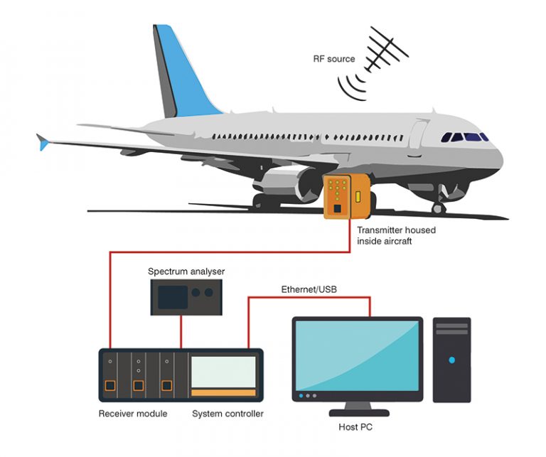
For both test methods, fiber optic links (FOLs) are essential to prevent compromising the measurements. For example, during low-level swept current and field measurements, FOLs are employed to provide signal gain and isolation from the generated electromagnetic (EM) environment, typically from 10 kHz to 1 GHz.
Prevent instrumentation influencing the aircraft’s transfer impedance
Instrumentation should not influence the aircraft’s transfer impedance whilst it is exposed to RF fields or simulated lightning (e.g. currents that degrade the airframe shielding). Interconnecting cables that pass from the external environment to the internal aircraft environment will impact measurements, as RF current can flow on the cable shields. It is therefore important that signal cables are not used to connect the external instrumentation to the field/current/voltage probes installed within the aircraft whilst performing frequency or time domain measurement, unless the cable is fibre optic (as used by PPM Test). This is particularly significant over the 10 kHz to 1 GHz frequency range, where cable coupling dominates the leakage mechanism into the aircraft under test.
Avoiding signal loss at high frequencies
The external test instrumentation must be outside the measurement area which, with large aircraft, may lead to a separation distance of tens of meters or more. Signal loss then becomes a significant factor at higher frequencies. This signal loss is completely mitigated by the use of FOLs. A typical low level swept current measurement in an aircraft would require signal cables of 40 to 50 meters, introducing significant losses. FOLs are typically used with fiber link lengths of 100 meters or more, permitting signals to be coupled (almost losslessly) from the transducers installed on the aircraft to the remote measurement equipment.