Bergoz Beam Position Monitors, BPM

MX-BPM Overview
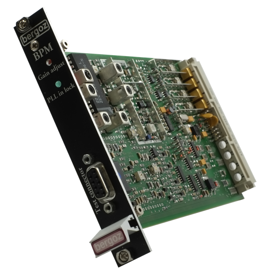
The Bergoz Multiplexed Beam Position Monitor (MX-BPM) is an electronics module with superior performance in a small volume. It is a non-intercepting system that has been optimized for use in electron and positron Storage Rings.
LR-BPM Overview
The Bergoz Log-Ratio Beam Position Monitor (LR-BPM) is an electronics module designed for fast processing of beam position signals. To achieve this, the signals are parallel processed in a single pass position measurement. It is a non-intercepting system that is suitable for use in most Linacs, transfer lines, first turns, boosters and fast-cycling synchrotrons.
MX-BPM features:
- On-board microstrip filters that eliminate the need for costly tubular filters
- GaAs switches to provide superior button to button isolation and low insertion loss
- On-board synthesized local oscillator to eliminate the problem of external oscillator signal distribution with power supplies
- Automatic Gain Control with a range of greater than 90dB provides optimum levels for the demodulator, independent of the beam intensity and number of bunches
- Phase-locked synchronous demodulation giving high lineariry and noise suppression
- Button signal range of -70dBm to +5dBm
- X & Y output level of ±10V.X & Y resolution of 1µm
- Sample rate of up to 10,000 samples per second.
The LR-BPM features
- Input signals are parallel processed allowing a single-pass position measurement.
- Beam charge range > 500
- Beam-based center determination
- Bunches at any repetition rate up to 500 MHz Individual bunches can be distinguished from one another up to 5 MHz repetition
- Log-Ratio BPM is plug compatible with Bergoz’ multiplexed BPM
- L-band, S-band, X-band beams can be processed provided bunch groups are short (<3 ns)
- ±2V X and Y outputs are held until the next bunch when Sample & Hold mode (optional) is activated.
- Provides log signal from each pickup electrode for computer analysis, with 5 MHz bandwidth.
- Beam-based center determiuation accessory equalizes pickup signals to simulate beam on center.
- The Log-Ratio Beam Position Monitor (LR-BPM) is an electronics module for fast analog processing of beam pickup signals
- LR-BPM may be custom-built on daughter card for installation on user’s DSP motherboards
- Cables length matching not critical pickup signals don’t need to be in phase
Tech Support
Accessories
Options for MX-BPM (factory installed):
MX-PBM-FG: Fast NIM Gate, to gate or gate-out a specific bunch or bunch train.
MX-BPM-IFOUT: IF frequency output for digital I/Q detection.
Options for LR-BPM (factory installed):
LR-PBM-SH: Sample and Hold on X and Y outputs.
LR-BPM-TRG: Beam Trigger.
LR-BPM-SUM: Output: Sum of Log (A, B, C & D).
LR-BPM-ABCD: Output: Direct Log (A, B, C & D), wideband outputs.
Other Accessories:
BPM-BBC: Beam based center determination for LR-BPM. Equalizes the inputs to simulate a centered beam. Requires in-phase pickup signals. User controlled via the LR-BPM module.
MXBPM/CUS-xxxMHz: One time engineering charge to customize a MX-BPM to a specific operating frequency.
BPM-RFC/xx: 19" Rack chassis with up to 16 Euromodule stations installed.
BPM-KIT: Table top test kit for one BPM, includes power supply.
BPM-XTD: BPM Euromodule extender.
BPM-SERV/RF: RF service module, connects button signals to four BNC connectors.
BPM-SERV/CMD: TTL commands service module, connects command lines to a panel mounted DB9 connector.
BPM-LPF/1kHz: X & Y output low pass filter.
BPM-BPF/500MHz: SMA - SMA input band pass filter.
BPM-UHV-50: Beam Pickup Assembly. A set of four buttons mounted in to a high vacuum tube with 3" a conflat flange on each end.
Pricing
| Quantity Discount Schedule: | |||
|---|---|---|---|
| Quantity | 2 – 4 | 5 – 9 | 10 – 24 |
| Discount | 3% | 7% | 10% |
Terms and Conditions
Terms and Conditions:
Prices above are for domestic deliveries to USA, Canada, and Mexico only.
For deliveries in all other countries please contact Bergoz.
Prices are expressed in U.S. Dollars, FCA San Carlos, California.
Prices are subject to change without notice.
Higher quantity and OEM discounts are available.
Payment:
Visa, MasterCard, Amex, Prepayment before shipment, or Net 30 days (subject to credit acceptance).
Delivery:
Stock to 90 days, depending on quantity.